Vehicle-based Mobile Mapping is the acquisition technology of choice for fast and accurate mapping of larger areas. But how accurate is Mobile Mapping actually, and how can accuracy be improved?
GNSS/INS positioning
Mobile Mapping systems use GNSS/INS positioning units (often named the IMU = inertial measurement unit). These combine one or several GNSS receivers (two is common to enable GNSS-based heading estimation) with inertial sensors (accelerometers and gyros) that measure acceleration in three directions and rotation around three axes (roll, pitch, yaw). A couple of decades ago the gyros were actual spinning gyros, but this is no longer the case. Cheaper units use piezo-based MEMS gyros, more expensive and accurate units employ fiber-optic (FOG) or ring laser (RLG) gyros.
Unlike some claims to the contrary, absolute accuracy is governed by GNSS accuracy. All tests I’ve done and a few sensitivity analyses I’ve seen clearly support this. The INS contribution is mostly in orientation estimation and for filling the gaps between the relatively coarse GNSS update frequency of usually 1 Hz. Without GNSS signal, such as in tunnels, position accuracy quickly degrades, especially with low-cost MEMS inertial units. Odometers that measure wheel rotation are a popular upgrade, but are of limited utility, too. They are often introduced in the trajectory computation with a 1% error, which amounts to 10m per kilometer… Their main benefit in my opinion is accurate detection of the acquisition vehicle being stationary (ZUPT – zero update), which is required to prevent drifting, especially when stationary in a location with poor GNSS reception.
Post-processing
While it is possible to compute the IMU trajectory in real time, I’m a firm believer in post-processing. This allows the use of multiple GNSS reference stations, accurate orbits (although they have less impact than they used to have a decade or two ago, as broadcast orbits have become more accurate), and doing forward and reverse computation of the trajectory. Trajectory processing employs a Kalman filter that fuses the observations of all sensors and produces not only the state vector with position and orientation parameters, but also estimates their accuracy. Additionally, adaptive Kalman filters are employed that can compute calibration values like odometer scale values and even antenna lever arms.
As trajectory accuracy is governed by GNSS accuracy, it’s the GNSS-related factors that impact absolute accuracy:
- Baseline length (distance to the reference station that is used)
- Satellite coverage
- Ambiguity fix quality
- Multipath
Forward/reverse computation and separation analysis
Post-processing makes it possible to not only do a forward computation of the trajectory (i.e. in the order in which the navigation data was acquired), but also in reverse direction. Ideally, both computations should yield the same results. In practice, this is not the case. Take for example the case of a tunnel:
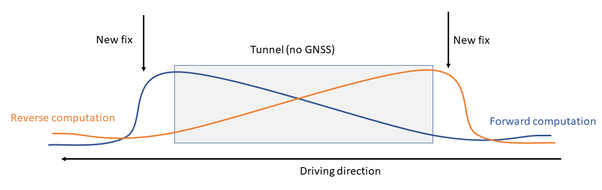 Here, the combination (averaging) of forward and reverse trajectory will provide a better result than using only the forward trajectory. Ideally, the combined trajectory would employ the best parts of either computation to get an optimum.
The difference between forward and reverse computation is called the separation. It is a much better estimate for the trajectory quality than the estimation position accuracy, which results only from the noise model and satellite geometry and thus does not take into account errors like wrong ambiguity fixes/cycle slips, and multipath. Take for example this trajectory, where the estimated position accuracy does not exceed 3cm, but the separation reaches 70cm at some point. How is that possible at supposedly 1.5cm position accuracy?
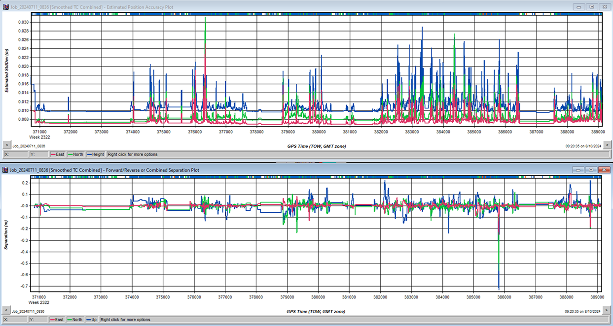
It is unlikely that both the forward and reverse computation are wrong – often, it is just one. Simply averaging across the differences will, in this case, result in an error of 35cm that also has a short duration and thus large gradient, and hence is difficult to detect and correct by using ground control points.
Smart combination
The goal is thus a smart combination of forward and reverse computation that takes the good parts of each instead if simple averaging, as even weighted averaging that takes into account the estimated accuracy will not deal with outliers like the one shown above, which is likely the result of a poor fix or multipath. But how to choose the better solution?
Luckily, here in the Netherlands we have accurate and reliable height data available. The AHN covers the entire country, whereas even higher resolution data of the rail network is available through SpoorInBeeld. By comparing the forward and reverse trajectories to the height data, it is possible to determine the “better” solution in locations with large separation.
This works under two assumptions:
- The IMU is at a fixed height above the ground, which should be the true except for suspension travel.
- Locations with poor quality/large separations always have large separations in Z direction, which in my experience is true.
A new trajectory can then be computed by selecting the better solution (forward or reverse), i.e. the one that matches the height data better, for locations with large separations, and sticking with the combined solution for those with small separations. This is implemented in my software TTools for trajectory analysis.
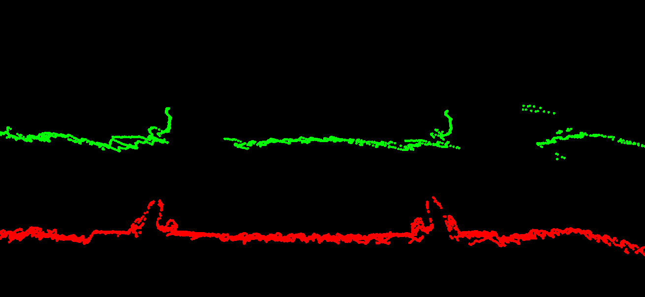
Below images illustrate the differences this makes at a location with a large separation (about 90cm in height) between forward and reverse computation. Shown are point clouds from two drivelines over adjacent tracks. The large separation results in an error of about 45cm in the combined trajectory:
After smart combination of forward and reverse computation, using only the better solution in this location, the resulting point clouds match very well:
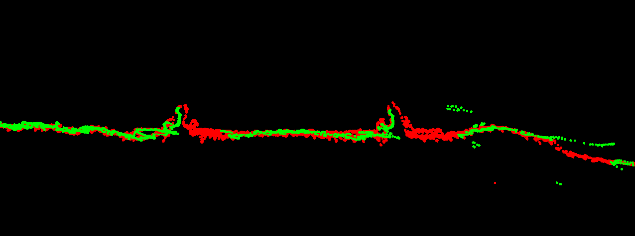
This shows the benefit of doing proper analysis and combination of both solutions instead of just averaging.
Driveline matching
So far, we’ve only considered individual drivelines. Yet one of the important geodetic principles is to measure multiple times to generate redundancy, get the best fit taking into account each observation’s accuracy (the stochastic model), and doing testing to tune the stochastic model and eliminate outliers. In Mobile Mapping, this can be achieved by matching overlapping point clouds from neighbouring drivelines, which is not an easy task.
The commercial implementations of this that I’ve seen so far allow for the use of the estimated position accuracy for weighting the individual drivelines. But as we’ve seen above, the estimated position accuracy is not a reliable measure as it does not take outliers into account. My own software, HaiQuality Adjust, solves this by implementing what is standard in geodetic network adjustment software: testing, using the normed residual (the correction divided by the a-priori estimated accuracy). If this testing parameters exceeds a certain threshold, the estimated accuracy is scaled, reducing the driveline’s weight in the overal solution. It is also possible to completely deselect drivelines. They will then still be matched onto the others, but do not contribute to the overal positioning of the point clouds, eliminating the effect of outliers.This matching creates not only improved data, but also provides an accurate measure of the resulting data’s accuracy at each matching location. This is equivalent to a list of coordinates with their adjusted accuracy as produced by network adjustment software, and makes it possible to specifically target problem areas, e.g. by using a higher density of ground control points.
Conclusions
Trajectory post-processing, analysis of the results (especially the resulting separation) and driveline matching are essential steps in the generation of accurate and reliable Mobile Mapping data. The estimated position accuracy as reported by the trajectory processing (whether in real-time or post-processing) is not a reliable measure of quality as it does not take outliers into account. The only way to obtain reliable accuracy values is by using redundancy, both from the forward/reverse computation and driveline matching.
